Installing
a case, fan and heatsink
If
you want to build a media player I seriously recommend using a case,
heatsink and fan combination. The PI can run rather hot when
streaming 1080 HD media. The pretty pink or black standard cases do
not have fittings for a fan or ventilation holes. After buying a pink
one and finding it ran too hot for my liking I decided to buy a clear
case with a fan for better cooling, you live and learn.
Ironically
the fan and case were cheaper.
Option
1 - Pink original case, also available in Black.
The
PI ready to be fitted in a pretty pink case


Fit
the Pi into the base first, put the end with the Led's in first, then
gently ease the rest in.


Fit
the side panels, they will only fit one way, look at the sockets for
clues, the cam and display sockets have blanks in to keep dust out.

Only
the two tops to go. Why two tops? Allows access for cam and other
'hats' (auxiliary PCB's)
Look
ventilation-


The
PI has got it's hat on!
Ready
to go!
Okay
- Option 2 - Clear case and Fan
Jigsaw
puzzle of parts

Fan
and mounting screws - note I do NOT like this connector, it can
easily short the pins on the next row! I used a different one as I
needed a power switch too.

Mount
the fan with it's screws, do tighten with a screwdriver and pliers.
Fans vibrate and make noise, more so if they are loose. I can hear
this across a quiet room! I have an idea to quieten it later.

Remember
fans should extract so make sure it is this way up. Check the orientation of
the slots, you may want to plug a display or camera in later. I got
it wrong first time!

If
you are just installing a fan it can go on pins (4) +5v and (6)
ground. I wanted something more ambitious. I did not use this
connector in the end.


There
is inly one ground pin at this end, so I made an adapter up.
Pins 4 and 6 to the fan, and pins 4 and 5 to the power switch. The
power switch needs software to work, I need to find better software for the power switch.
Wires twisted and checked ready to solder.


You
may get away without soldering if you are very careful but I
recommend soldering and taping properly. I do have a background in
Electronics, so I will not bodge the job.

Wires
soldered and trimmed neatly, less to go wrong.

I
prefer to tease the wires so that they flow naturally rather than
double back. Prepare some insulating tape length with a sharp knife
or scissors. It is much neater then ripping the tape and risking
damaging thin wires.


Neater
is safer - meticulously prepared! I shortened all the wires as they
will foul the fan and are not easy to fold up inside the case. (Red
is positive 5v on the fan and Black is ground, the power switch does
not matter which way round it is)

Ignore
the legend on the (new) fan connector, this is the fan connection. If
that is all you are doing, read no further!

The
Blue wire connecting to pin 1 is redundant. I cut it short but left enough to
re-use if I choose to. (That's called a service length, around 25mm
or 1inch)


Heatsinks
were installed prior to writing this, they just stick on, keep them
central on the chips. One on CPU/GPU and one on the Northbridge chip.
Wiring
Diagram for power and fan combo.
This
is for a PI rev 2 only - you
could also do a reset switch too. For other versions there are plenty
of articles.

Pin
4 +5v - to Fan Red wire
only
on a PI 3 rev 2, others use may pin 2 as pin 4 is NC - do not connect
so check!
Pin
5 GPIO9 - to power switch
Pin
6 ground - to Fan black wire and Power switch other wire.
Or
if you want to know more -


The
back case panel, see the slot for the SD card, I had to mod the case
side later as SD is not removable easily with the case assembled.
This might not be a problem unless you wish to experiment, but that
is why I bought a PI.

Case
coming together, you need good dexterity and many hands, or a friend.

Almost
there, laying things out give you time to check before you assemble,
you can test it first.

The
power switch is a reset switch from an old PC, a power switch will do
too if it is momentary contact, i.e. non latching. Or visit Maplin or
Ebay or other electronics shops.

The
end near the fan needs to fit between the sides without pushing them
apart, this forms a primitive hinge. the end nearest has to be gently
clipped into place, it has spring cut-outs to old the whole case in
place.
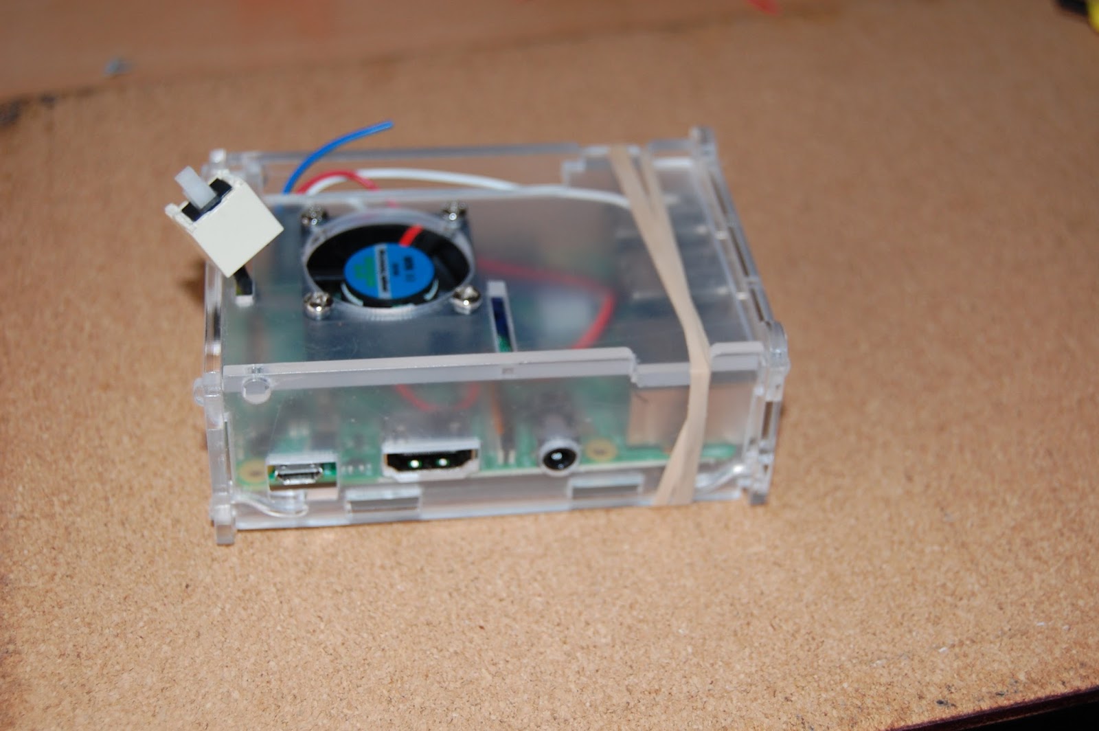
The
wires want to push the case apart, elastic band to the rescue. You
could use a dab of hot-glue or PVA adhesive once you have tested and
made sure you can access the SD slot.

Looking
great! Power and HDMI connected.
Now to program the Fan Control